What BlackBox3 Does
BlackBox3 constructs an xml diagnostic gauge that can be used to display in readout form or HDD file the numerical or string values of all or selected A:, E:, G:*, L:, and P: variables of the gauge you are editing/building. It can display important parameters such as L: and A: variables, booleans, enums, etc., that are not often displayed directly by the gauge you are building. As such, it is very useful for debugging xml gauge logic; you can see what all variables are doing in real time as MS Flight Simulator flies.
The BlackBox3 application can be used with either FS9 or FSX and requires installation of the Logger module which can be downloaded from this website. Please follow the installation instructions for Logger as well as the Setup instructions for Blackbox3 which are included in the Help file for each product.
The BlackBox3 'Gauge'
The BlackBox3.jar application creates an xml gauge file (the 'BB3' file as described below) using FS2004 (FS9) gauge syntax. You add this gauge in your Panel.cfg file, and its xml code produces the BlackBox3 output display or hard disk in real time when MSFS is running.
As well, information about all gauges that are added to BlackBox3 and all variables that have been selected for display is stored in the comment section of the file. Consequently, one can think of this file as either the BlackBox3 "gauge" file (it is the BlackBox gauge identified in Panel.cfg), or the BlackBox3 "output" file (it is output by the BlackBox3 program and contains xml instructions to generate the output display), or the BlackBox3 "project" file (it stores all gauges added and variables selected).
Setup 1 - edit Panel.cfg
BlackBox3 output is designed to be displayed in a separate window within MSFS. Define this window by editing the Panel.cfg file.
-
Edit the
[Window Titles]section. As an example, the default FSX Beech Baron 58[Windows Titles]section is shown below:[Window Titles]Identify a BlackBox3 window title by adding a line for BlackBox3 and choosing a new window number (Window06 in this example):
Window00=Main Panel
Window01=Radio Stack
Window02=GPS
Window03=Throttle Quadrant
Window04=Compass
Window05=Mini Panel
        			[Window Titles]

        			Window00=Main Panel

        			Window01=Radio Stack

        			Window02=GPS

        			Window03=Throttle Quadrant

        			Window04=Compass

        			Window05=Mini Panel
Window06=BlackBox3 -
Define the BlackBox3 window by adding a new
[Window__]section such as:[Window06]Parameter selection:
size_mm= 400, 700
visible=1
gauge00=Custom_Gauges!BB3, 0, 0, 400, 700
- size_mm= In a single monitor configuration, choose a window size sufficiently smaller than the main
panel size_mm in order to see the BlackBox3 output display plus an adequate amount of the main panel. For example, with
a 1024x768 main panel image, a BlackBox3 window
size_mm=400, 400orsize_mm=400, 700might be sufficient. - size_mm= For multiple monitor configurations, you may want to choose a BlackBox3 window size that is
as large, or nearly as large as the main panel size. If your main panel image is 1024x768, a BlackBox3 window
size_mm=1000, 750may be a good choice. When the BlackBox3 output display window is open in MSFS, right click it to Undock, and then drag it to the other monitor. - visible=1 is used to display the BlackBox3 window when the aircraft is initially loaded. Visible=0 will cause the BlackBox3 window to remain hidden until it is selected for display by the MSFS drop down 'Menu Views' - 'Instrument Panel' - 'BlackBox3'. Note you can always right click the BlackBox3 window, select 'Undock Window', and move the BlackBox3 display around the screen as desired.
- gauge00= Choose a BlackBox3 gauge name such as BB3, or make the gauge name more aircraft specific, for example C421_BB3, and identify its folder (Custom_Gauges folder in this example) as you would other gauges you are editing/building. X and Y position should be set to 0, 0. It is suggested the BB3 gauge 'X size' and 'Y size' be set equal to the BlackBox3 size_mm window size (400, 700 in this example).
- size_mm= In a single monitor configuration, choose a window size sufficiently smaller than the main
panel size_mm in order to see the BlackBox3 output display plus an adequate amount of the main panel. For example, with
a 1024x768 main panel image, a BlackBox3 window
The BlackBox3 window should be installed as the last panel section in Panel.cfg, preferably below the Virtual Cockpit section(s), in order to obtain the correct value of L:Vars. Otherwise, an L:Var being updated in another part of the panel may not express the proper value in the BlackBox3 gauge.
Setup 2 - edit BB3Settings.xml
-
Edit line 4 of the BB3Settings.xml file specifying the same size values as defined in Panel.cfg, above. In BB3Settings, 'Width' is equivalent to the Panel.cfg 'X size'; 'height' is equivalent to 'Y size'. Following the Panel.cfg example above, BB3Settings line 4 would read:
<gauge width="400" height="700" fillcolor="Black" font="Arial" />Use whatever Window and gauge size you established for the BlackBox3 Window in your Panel.cfg file.
Fillcolor and font do not need to be edited at this time. Please read Modifying BlackBox3 Output Display (below) for discussion of these settings.
Note - The BlackBox3.jar application must always be closed while editing BB3Settings.xml.
-
Edit line 8 of the BB3Settings.xml file to specify the file path to be used for Blackbox3 output to file. List only the file path but do not include the file name and extension. Those will be added when Flight Simulator is running, as explained in the output display format section of this Help file. For example:
<logger path="C:\Documents and Settings\username\Desktop\BB3 Files\" />Note - The BlackBox3.jar application must always be closed while editing BB3Settings.xml.
Initial Operation 1 - select gauges and variables
-
Launch BlackBox3 by double clicking the BlackBox3.jar icon. BlackBox3 will open with the last BlackBox3 gauge,
or "project" file, you were working on. If you wish to open another BlackBox3 project file, choose 'File' - 'Open' from the
Menu, and browse for the file. The loaded BlackBox3 gauge name will appear on the BlackBox3 Title Bar.
Note - Opening an existing project file may take a few seconds, especially if it contains many gauges or gauges with significant numbers of variables. Each time an existing project file is opened, BlackBox3 must read and parse line-by-line all gauges included in the project.
-
Add Gauge: Click and Drag the xml gauge file you are editing or whose variables you wish to view as MSFS flies into the
opened BlackBox3.jar application. Alternatively, select the 'Add Gauge'
 icon from the Toolbar
to add an xml gauge file you are editing. The gauge variables will appear as a separate tab.
icon from the Toolbar
to add an xml gauge file you are editing. The gauge variables will appear as a separate tab.
- Select Variables: BlackBox3 will list all variables except G: found in your gauge. After opening the gauge (Step 2), select or de-select the variables that you want displayed as Flight Simulator runs by clicking anywhere on the variable name. You can select all or select no variables though use of the 'Select All' or 'Select None' buttons. Once selected, the variable name is bolded, and the check box is checked. Please note that G: variables cannot be read by other gauges. Consequently, the BlackBox3 xml gauge will not have access to your gauge's G:Vars and will therefore overlook those variables if they exist in your gauge. Read the suggested workaround for this limitation, below.
-
Sort: BlackBox3 initially lists the variables by order of occurrence in your xml file. If you wish to sort the BlackBox3
readout display differently, choose 'Edit' - '
 Sort By ...' from the Menu. Variables can be sorted according to order of
Occurrence, Type, Name, Units, or Checked (selected) variables.
Note - your gauge xml file is never affected by BlackBox3 - sorting only changes the order that BlackBox3 displays the variables.
Sort By ...' from the Menu. Variables can be sorted according to order of
Occurrence, Type, Name, Units, or Checked (selected) variables.
Note - your gauge xml file is never affected by BlackBox3 - sorting only changes the order that BlackBox3 displays the variables. -
Add Additional Gauges: If desired, add additional gauges by repeating steps 2 through 4. Additional gauges appear as new
tabs. To remove a gauge, click the
 (x) on the right side of the tab name.
Note - Selecting excessive numbers of variables to simultaneously display on the screen, while possible with BlackBox3, is not only difficult for the eye to keep up with, but also can have a significant negative impact on frame rate.
The number of gauges included in a BlackBox3 project file does not affect frame rate; you can add as many as you want. However, frame rate can be affected by the number of variables displayed simultaneously. 'Tabbed' BlackBox3 output format (below) may be able to mitigate this by managing the number of gauges that BlackBox3 displays at one time. Additionally, selecting fewer variables to display will improve frame rate.
Alternatively, file output (Logger Format) has negligible effect on frame rate, even if hundreds of variables are written to file each gauge update cycle.
Initial Operation 2 - choose BlackBox3 output display format
BlackBox3 screen output can be configured several ways: 1) Single Column, 2) Wrapped Output, 3) Tabbed Single Gauge, 4) Tabbed Multiple Gauge, or two file output formats, 1) Logger - CSV or 2) Logger - Newline.
-
Choose Output format from the BlackBox3 Menu 'Edit' - '
 Output Format ...':
Standard Format: In Standard Format, the selected variable lists for all gauges are displayed.
- Single Column format displays the selected variables in one column, one gauge below the other. The gauge file name appears at the top of the list of its variables. A slider is located on the right side of the BlackBox3 output display for vertical scrolling of BlackBox3 output, if needed. The mouse scroll wheel will work, as well.
- Wrapped Output format is similar to Single Column format in that selected variables are displayed one gauge below the other, however, the display wraps to successive columns if the number of selected variables exceeds the BlackBox3 window height. A slider is located on the bottom of the BlackBox3 output for horizontal scrolling, if needed.
Tabbed Format: The advantage of Tabbed Format is that the number of gauges displayed at one time can be controlled (i.e., limited) dynamically. When a Tabbed Format is selected the top row(s) of the BlackBox3 output will display a Tab for each gauge included in the BlackBox3 project. Clicking on the tab toggles the display for that gauge.
- Tabbed Single Gauge Output displays the selected variables of a single gauge at a time. Clicking a tab opens the variables display for that gauge and closes the display of all other gauges in the project. In Tabbed Single Gauge format, the variables list is wrapped onto successive columns as required. A slider is located on the bottom of the BlackBox3 display for horizontal scrolling, if needed.
- Tabbed Multiple Gauge Output displays the selected variables of any gauge, or gauges, you choose. Clicking
a tab toggles open/close the display for that gauge. Clicking additional gauge names opens the variables
display for those gauges. In Tabbed Multiple Gauge format, the selected variables list for each gauge is confined to a
single column. Sliders are located on the right and bottom of the BlackBox3 display for vertical and horizontal
scrolling, if needed. As well, the mouse scroll wheel can be used for vertical scrolling.
Note - When changing from Tabbed Multiple to Tabbed Single format or vice versa, character overwriting or column placement errors may initially occur. Click any Tab and the errors will clear.
Logger Format (File output): Selected variables are output to a file on your hard disk rather than displayed on the screen.
- Logger - CSV writes all variables on one line of the output file, each record separated by a comma. With each new gauge update cycle, variables are written on a new line. The first line, or row, of the output file contains the variable name for reference. Logger - CSV is the recommended choice for Blackbox file output.
- Logger - Newline writes each variable on a new line of the output file.
-
Save then Reload: Every time the Output Format is changed from the Menu ('Edit' - '
Output Format ...'), the BlackBox3 output file must be Saved and the BlackBox3 gauge Reloaded into MSFS.
Refer to steps 5 and 6 from Subsequent Operation, below.
- Units: Output of any format can be configured to display the variable's units, if desired. Toggle units display on or off by selecting 'Edit' - 'Show Units' from the BlackBox3 Menu.
Initial Operation 3 - save the BlackBox3 xml file
- Save As: Select 'File' from the BlackBox3 Menu, choose 'Save As' and give the BlackBox3 output xml file the same name used in the Panel.cfg file, for example, "BB3". Note that it isn't necessary to .cab your gauge or BlackBox3 xml files as you build your gauge.
- Run MS Flight Simulator: The BlackBox3 gauge appears in a separate window as a list of the selected gauges and variables and their associated real-time values. Default settings use white lettering on a black background. The default number format is 13.2f. Exceptions to this are Booleans, Enums and other integer variables (Absolute Time, kilohertz) which are displayed as 13d, Megahertz which is displayed as 13.3f, and Latitude or Longitude variables which are displayed as 13.4f. BlackBox3 displays 'string' units as 13s. Display formats of any variable can be changed as described below.
- Windowed Mode, Not Full-Screen: It is suggested that MSFS not be run in Full Screen view mode while using BlackBox3. This way, MSFS and the BlackBox3 application can be running simultaneously, with the BlackBox3 application minimized to the Windows Taskbar when input to BlackBox3 is not required, but maximized when it is.
Subsequent Operation
After you make further edits to the gauge(s) you are building, or if you want to add gauges, change output display format, or simply select different variables to display in BlackBox3:
- Maximize or re-launch BlackBox3. It remembers the file names, file paths and selected variables that you were last working on.
-
Reparse: Select 'Reparse'
 from the Toolbar. This will update BlackBox3 with the latest variables added or
changed in the gauge(s) you are building.
from the Toolbar. This will update BlackBox3 with the latest variables added or
changed in the gauge(s) you are building.
- Gauge and/or Variable selection and sorting: Add or delete gauges from BlackBox3 or select /de-select variables. Re-sort as desired.
-
Output Format: Change BlackBox3 output display format if desired.
Asterisks: If the BlackBox3 output display has changed because of addition or deletion of gauges, changed variable selection, or changed output format, then an asterisk (*) will appear next to the gauge name in the gauge Tab and the Output file name on the BlackBox3 Title Bar. This is a reminder that the BlackBox3 output file must be saved before the output display will reflect the changes. Once saved, (Step 5) the asterisks disappear.
-
Save BlackBox3 xml file: Click the 'Save' icon
 on the Toolbar or select 'File' from the Menu and choose 'Save'. This
will save your new selections and/or output format by overwriting the file BB3.xml. Alternatively, you can choose 'Save As' to
give the BlackBox3 gauge a new file name. In this case, of course, you will need to edit Panel.cfg again to change the BlackBox3
gauge name.
Hint - Use the keyboard shortcut 'ctrl+S' to speed up the process of saving your updated BlackBox3 file. Other available shortcut keys are identified in the Menu dropdown lists.Error Message - Unable to Create (Save) Gauge!: This error message is displayed when Save is attempted but the output file cannot be written to because it is being used by MSFS. The BlackBox3 output/gauge file must be unloaded from MSFS before it can be re-saved. You can Unload it by clicking the Unload/Reload icon
on the Toolbar or select 'File' from the Menu and choose 'Save'. This
will save your new selections and/or output format by overwriting the file BB3.xml. Alternatively, you can choose 'Save As' to
give the BlackBox3 gauge a new file name. In this case, of course, you will need to edit Panel.cfg again to change the BlackBox3
gauge name.
Hint - Use the keyboard shortcut 'ctrl+S' to speed up the process of saving your updated BlackBox3 file. Other available shortcut keys are identified in the Menu dropdown lists.Error Message - Unable to Create (Save) Gauge!: This error message is displayed when Save is attempted but the output file cannot be written to because it is being used by MSFS. The BlackBox3 output/gauge file must be unloaded from MSFS before it can be re-saved. You can Unload it by clicking the Unload/Reload icon (the "Reload" icon) located in the lower right corner of the BlackBox3 gauge. After the gauge is unloaded, click 'Try Again' to
save the file. Finally, after the file is saved (and the asterisk disappears), you must click the Reload icon again, as
described in Step 6.
(the "Reload" icon) located in the lower right corner of the BlackBox3 gauge. After the gauge is unloaded, click 'Try Again' to
save the file. Finally, after the file is saved (and the asterisk disappears), you must click the Reload icon again, as
described in Step 6. -
Reload_Panels: If MSFS is already running, you must Reload the panel gauges or the entire aircraft into MSFS in order for
gauge edits and BlackBox3 changes to appear. Clicking the Reload icon in the lower right corner of the BlackBox3 gauge
accomplishes a gauge panel Reload by keying the K:RELOAD_PANELS event in MSFS. This saves time by eliminating the need to close
and re-open the aircraft. Additionally, please note that you can Unload the panel xml files - releasing them from MSFS so they
can be read and edited by your xml editor - also by clicking the Reload icon .
Hint - If your gauge edit involves only gauge logic changes, but no new variables are added or existing variable names or units changed, then the BlackBox3 output file will not need to be re-Saved. In this case, simply Reload your gauge into MSFS by clicking the Reload icon .
- Run MS Flight Simulator.
Logger Operation - recording to file
A tremendous amount of data can be recorded to file using Logger. As many as ~ 750 different number or string variables of any type (A:, E:, P:, or L:) can be written to file each gauge update cycle, even when recording every cycle at an update frequency of 18 cycles per second. Unless some cycles are skipped between recordings, the output file will get very large, very rapidly.
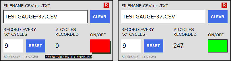
When Logger output format is selected, the Blackbox display will show the dialog box above instead of the usual variable read-out lists. To operate the Blackbox3 recorder, first click the white FILENAME.CSV text box to enable keyboard entry, and then type the desired file name. Include the file extension .csv (or .txt in Newline format), but do not include the entire file path here. Click the text box again to disable keyboard entry of the file name.
Click the white RECORD EVERY "X" CYCLES entry box and enter the frequency of Logger recording. A value of 1 means that Logger will write the selected variables to file every update cycle. A value of 18 means every 18th update cycle, and so forth. Blackbox3 uses the default 18 cycles per second Update frequency. Click the entry box again to disable keyboard entry.
Finally, click the ON/OFF button to start and stop the flight data recorder.
Displaying GVars
Add the following in the <Update> section of the gauge you are editing/building:
        (G:Var1) (>L:GVar1, number) (G:Var2) (>L:GVar2, number) (G:Var3) (>L:GVar3, number)

        (G:Var4) (>L:GVar4, number) (G:Var5) (>L:GVar5, number) (G:Var6) (>L:GVar6, number)

        (G:Var7) (>L:GVar7, number) (G:Var8) (>L:GVar8, number) (G:Var9) (>L:GVar9, number)
BlackBox3 will list variables named L:GVar1 through L:GVar9. The GVar values that your gauge generates can now be displayed as L:GVar1, etc.
To display GVar values in a multiple gauge BlackBox3 project, make the L: names gauge specific. For example, in the
<Update> section of an Altimeter gauge, (G:Var1) (>L:MyAlt_GVar1, number) and in the
<Update> section of, say, a Vertical Speed gauge, (G:Var1) (>L:MyVSI_GVar1, number), etc.
Displaying Any FS Generated Variable
To display any MS Flight Simulator variable, add the Simulation Variables.xml file (included with the BlackBox3 download) to the BlackBox3 "project". Simulation Variables.xml is a list of almost all A, E, and P variables (1, 186 count) identified in the FSX SDK, configured using common English units. Select any of these FS variables to display in BlackBox3 output. A typical BlackBox3 project might include this file so that any MSFS variable readout can easily be selected for view, 'on the fly', as FS runs.
Note - Care should be taken to verify that the index numbers listed in Simulation Variables.xml are correct for your aircraft. Additionally, Helicopter Specific variables should not be selected for BlackBox3 output display if a fixed wing aircraft is loaded in MSFS. Attempting this will cause MSFS to crash to desktop.
Alternatively, add FS variable name(s) to any gauge included in the BlackBox3 project within a comment, for example:
<!-- (A:AUTOPILOT GLIDESLOPE HOLD, bool) (A:GROUND ALTITUDE, feet) -->
BlackBox3 parses your gauge file for parentheses and gauge name syntax, so it can find MSFS variable names even within a comment.
Modifying BlackBox3 Output Display
<equate key ______ /> line edits of BB3Settings.xml, and all
settings parameters should be enclosed in quotes. For color selections, use color "#" format or choose
"Aqua", "Black", "Blue", "Fuchsia
", "Gray", "Green", "Lime", "
Maroon", "Navy", "Olive", "Purple",
"Red", "Silver", "Teal", "White
", or "Yellow".- Close/Exit the BlackBox3 application.
- Edit BB3Settings.xml:
- BB3 Gauge fill color: Edit line 4 to change the fill color of the BlackBox3 output gauge. The default
color is "
#000000" or "Black". - Font: Edit line 4 to change font type. Default is Arial.
- Font size: To change the size of the display text, edit line 4,
width="____" height="____". Increasing the values has the effect of zooming out; decreasing the values has the effect of zooming in. Retain the same aspect ratio if the values are changed. - Gauge Title color: Edit line 5 to change the text color of the gauge title (i.e., gauge name) in BlackBox3 output. The default color is "
#00ff00" or "Lime". -
Tabbed Output Format: Edit line 7 to change text color and background shading color of Tabbed Output as
follows:
<tab color="gray" background="#080808" selectedColor="#008800"
        				selectedBackground="#dddddd" />
color is text color of the gauge name in the 'non-selected' (not clicked) state
background is the background shading color of the tab in the 'non-selected' (not clicked) state
selectedcolor is text color of the gauge name when the tab is 'selected', or 'clicked'
selectedBackground is the background shading color of the tab when the tab is 'selected', or 'clicked'
- Variables color: Edit line 6 to change the text color of the selected variable lists in BlackBox3 output.
The default color is "
#ffffff" or "White". -
Number format: Edit line 6 to change the default number format (default format is 13.2f). Exceptions to the default format are found beginning on line 11. These formats can be changed if desired, and additional format exceptions can be added.
Note that there are
<units>and<name>sections in the BB3Settings file where the exceptions to the default number format are defined. Within<units>, all variables with the identified units type will be displayed using your prescribed number format. For example, in the default BB3Settings file all variables with an rpm unit are defined to be displayed using a 13d number format (see line 20).Within
<name>, individually named variables will be displayed using the prescribed number format. For example, in the default BB3Settings file the variable absolute time is defined to display using a 13d number format (see line 23).<name>exceptions take precedence over<unit>exceptions. - Line 3,
<file name="___________" />should not be changed.
- BB3 Gauge fill color: Edit line 4 to change the fill color of the BlackBox3 output gauge. The default
color is "
- Save BB3Settings.xml.
- Launch BlackBox3 then Save output file: To incorporate changes of the BB3Settings file into BlackBox3 output, re-launch BlackBox3 and then click the 'Save' icon on the Toolbar. This will generate a new BlackBox3 output file with the revised size & format settings.
- If MSFS is already running, Reload the BlackBox3 gauge into MSFS by clicking the Reload icon .
Changing the Order of Gauges in BlackBox3
With the Blackbox application open, Click and drag the gauge tab to the desired position.
BlackBox3 File Information
Input File: Any text file can be read by BlackBox3. Normally, the input file will be the xml gauge file you are editing/building. However, .txt, .ini, etc. text files can also be read and parsed for FS xml gauge syntax.
Output File:BlackBox prevents saving the output file using 'Save As' with the same name as the input file to avoid accidentally overwriting the gauge you are editing/building. As an additional safeguard, the following comment is added as the first line of BlackBox output files ("BlackBox2" is correct):
<!-- BlackBox2 Gauge
BlackBox will not save it's output file using 'Save' or 'ctrl+S' unless this comment appears as the first line of the file. This is meant to prevent accidental saving using 'Save' to an xml file not generated by BlackBox.
Write File Limitations and FS Cycle Time-out Limit
Writing data to hard disk is one of the most time consuming operations a gauge can undertake. Unlike the Flight Simulator gps module (in which data base searches can also be very time consuming) that operates asynchronously with your gauge, Logger is synchronous with the host gauge, so it is possible to reach the update cycle time-out limit of around 55 milliseconds before all data have been written to hard disk.
The numbers of records that can be written to hard disk each update cycle is dependent upon the hard drive capability, system resource load, and especially gauge complexity. It is independent of update cycle frequency. During tests using a fairly simple gauge such as Blackbox3 file output, around 750 different variables were written to hard disk every update cycle (with Update running 18 cycles per second) before exceeding the cycle time-out limit and losing some records.